CONTENTS
1 Scope..................................................................................................................... 10024
1.1 Overview ...................................................................................................... 10024
1.2 Specifications ............................................................................................... 10025
1.3 Conformance ................................................................................................ 10025
2 Normative references ............................................................................................. 10025
3 Terms, definitions, abbreviations, symbols and conventions .................................... 10027
3.1 Referenced terms and definitions .................................................................. 10027
3.2 Additional terms and definitions for distributed automation............................. 10028
3.3 Additional terms and definitions for decentralized periphery........................... 10030
3.4 Additional terms and definitions for media redundancy................................... 10038
3.5 Abbreviations and symbols............................................................................ 10039
3.6 Additional abbreviations and symbols for distributed automation .................... 10040
3.7 Additional abbreviations and symbols for decentralized periphery .................. 10040
3.8 Additional abbreviations and symbols for media redundancy.......................... 10041
3.9 Conventions ................................................................................................. 10042
4 Concepts................................................................................................................ 10044
5 Data type ASE........................................................................................................ 10044
5.1 General ........................................................................................................ 10044
5.2 Formal definition of data type objects ............................................................ 10047
5.3 FAL defined data types ................................................................................. 10048
5.4 Data type ASE service specification .............................................................. 10090
6 Communication model for common services ............................................................ 10090
6.1 Concepts ...................................................................................................... 10090
6.2 ASE data types............................................................................................. 10090
6.3 ASEs............................................................................................................ 10091
7 Communication model for distributed automation..................................................... 10191
7.1 Concepts ...................................................................................................... 10191
7.2 ASE data types............................................................................................. 10197
7.3 ASEs............................................................................................................ 10201
7.4 ARs.............................................................................................................. 10419
7.5 Summary of FAL classes............................................................................... 10423
7.6 Summary of FAL services ............................................................................. 10424
8 Communication model for decentralized periphery................................................... 10428
8.1 Concepts ...................................................................................................... 10428
8.2 ASE data types............................................................................................. 10444
8.3 ASEs............................................................................................................ 10444
8.4 Behavior of an IO device............................................................................... 10680
8.5 Behavior of an IO controller .......................................................................... 10724
8.6 Application characteristics............................................................................. 10728
Annex A (informative) Device instances....................................................................... 10730
Annex B (informative) Components of an Ethernet interface......................................... 10732
Annex C (informative) Scheme of MAC address assignment ........................................ 10736
– 10004 – 61158-5-10/FDIS © IEC
Annex D (informative) Collection of objects ................................................................. 10737
Annex E (informative) Measurement of the fast startup time......................................... 10738
Bibliography.................................................................................................................. 10739
FIGURES
Figure 1 – Data type class hierarchy example................................................................ 10045
Figure 2 – NetworkTime date relation ............................................................................ 10068
Figure 3 – PTCP applications........................................................................................ 10104
Figure 4 – Clock drift measurement............................................................................... 10115
Figure 5 – Multiple synchronization ............................................................................... 10115
Figure 6 – MRP stack.................................................................................................... 10118
Figure 7 – Ring topology with one manager and clients.................................................. 10129
Figure 8 – MRM in an open ring .................................................................................... 10129
Figure 9 – More than one MRM in the ring..................................................................... 10130
Figure 10 – Media redundancy diagnosis dependencies................................................. 10131
Figure 11 – Locating the destination for redundant RT frames........................................ 10171
Figure 12 – Example of periods at a local port ............................................................... 10178
Figure 13 – FAL ASEs communication architecture........................................................ 10193
Figure 14 – Runtime object model ................................................................................. 10194
Figure 15 – Relationship between engineering and runtime............................................ 10195
Figure 16 – Navigation in the runtime object model........................................................ 10196
Figure 17 – Operating state block diagram .................................................................... 10235
Figure 18 – Device status model for the common diagnosis ........................................... 10236
Figure 19 – ACCO ASE structure .................................................................................. 10267
Figure 20 – Productive operation of data connections .................................................... 10268
Figure 21 – Quality code transfer – standard behavior ................................................... 10280
Figure 22 – Startup of a connection............................................................................... 10281
Figure 23 – Quality code with communication fault......................................................... 10281
Figure 24 – Quality code when a connection is cleared .................................................. 10282
Figure 25 – Quality code when a connection is deactivated............................................ 10282
Figure 26 – Quality code during the transfer of "incorrect" connection data..................... 10283
Figure 27 – Quality code for provider in "CBAReady" state ............................................ 10284
Figure 28 – Quality code when clearing an object from the provider ............................... 10284
Figure 29 – Quality code when a connection is forced.................................................... 10285
Figure 30 – Quality code at QoS violation...................................................................... 10285
Figure 31 – Push mode ................................................................................................. 10292
Figure 32 – Pull mode overview..................................................................................... 10293
Figure 33 – Detailed sequence chart of the pull mode.................................................... 10294
Figure 34 – QoS and ORPC communication channel ..................................................... 10295
Figure 35 – QoS Violation within Pull Mode ................................................................... 10296
Figure 36 – Monitoring the providers heartbeat.............................................................. 10297
Figure 37 – State machine RemoteACCO ...................................................................... 10299
Figure 38 – State machine RemoteACCOProvider ......................................................... 10299
Figure 39 – State machine RemoteACCOProviderORPC ................................................... 10300
Figure 40 – State machine ARORPC – Provider................................................................ 10300
Figure 41 – State machine GetConnectionData – Provider ............................................. 10301
Figure 42 – State machine ProviderConnection ............................................................. 10301
Figure 43 – State machine ProvConnActivation ............................................................. 10302
Figure 44 – State machine WorkerORPC....................................................................... 10302
Figure 45 – Communication stack of distributed automation devices .............................. 10303
Figure 46 – Application relations between devices ......................................................... 10304
Figure 47 – Communication relations............................................................................. 10304
Figure 48 – RT communication channel......................................................................... 10306
Figure 49 – Interaction between provider and consumer ................................................ 10308
Figure 50 – State machine ARSRT – Consumer............................................................... 10310
Figure 51 – State machine ARSRT – Provider.................................................................. 10311
Figure 52 – State machine AccoDataCR – Consumer..................................................... 10312
Figure 53 – State machine AccoDataCR – Provider ....................................................... 10312
Figure 54 – RT frame layout.......................................................................................... 10313
Figure 55 – Establishing an AccoDataCR ...................................................................... 10314
Figure 56 – Flowchart of the copy cycle for local connections ........................................ 10315
Figure 57 – State machine connect attempt ................................................................... 10319
Figure 58 – Productive operation of data connections (ORPC channel) .......................... 10326
Figure 59 – Productive operation of data connections (RT channel) ............................... 10327
Figure 60 – Productive operation of data connections (Local channel)............................ 10327
Figure 61 – Data flow for cyclic RT................................................................................ 10328
– 10006 – 61158-5-10/FDIS © IEC
Figure 62 – Failure of the provider in productive operation (ORPC push mode) .............. 10330
Figure 63 – Failure of the provider in productive operation (ORPC pull mode) ................ 10331
Figure 64 – Scenario 1: Provider failure in productive operation (RT) ............................. 10332
Figure 65 – Scenario 2: Recovery from provider failure in productive operation (RT) ...... 10333
Figure 66 – Failure of the consumer (push mode) .......................................................... 10333
Figure 67 – Failure of the consumer (pull mode) ............................................................ 10334
Figure 68 – Failure of the consumer .............................................................................. 10335
Figure 69 – Failure of the provider when setting up connections .................................... 10337
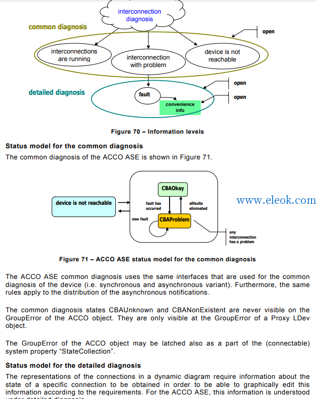
Figure 70 – Information levels ....................................................................................... 10338
Figure 71 – ACCO ASE status model for the common diagnosis .................................... 10338
Figure 72 – ACCO ASE status model for the detailed diagnosis ..................................... 10339
Figure 73 – Structure of the transmitted connection data ............................................... 10382
Figure 74 – Example of communication between controlling devices and field devices.... 10429
Figure 75 – Example of communication between an engineering station and several
controlling and field devices ........................................................................... 10429
Figure 76 – Example of communication between field devices and a server station ........ 10430
Figure 77 – Example of communication between field devices........................................ 10430
Figure 78 – Structural units of one arbitrary API of an IO device (general)...................... 10432
Figure 79 – Example 1 structural units for interfaces and ports within API 0 ................... 10433
Figure 80 – Example 2 structural units for interfaces and ports within API 0 ................... 10434
Figure 81 – Overview of application processes .............................................................. 10436
Figure 82 – IO device with APs, slots and subslots ........................................................ 10437
Figure 83 – Application Process with application objects (APOs).................................... 10440
Figure 84 – Access to a remote APO............................................................................. 10441
Figure 85 – Access to a remote APO for provider/consumer association ........................ 10442
Figure 86 – Example of one AR with two AREPs............................................................ 10443
Figure 87 – Relation of a record data object to one real object....................................... 10445
Figure 88 – Relation of a record data object to two real objects...................................... 10446
Figure 89 – Overview IO ASE service interactions ......................................................... 10456
Figure 90 – Example of a resource model at the alarm source ....................................... 10533
Figure 91 – General isochronous application model (example)....................................... 10568
Figure 92 – ASE relations in an IO device operating in isochronous mode...................... 10574
Figure 93 – State machine relations in an IO device operating in isochronous mode....... 10574
Figure 94 – SyncCtl state diagram................................................................................. 10578
Figure 95 – Output state diagram .................................................................................. 10580
Figure 96 – Input state diagram..................................................................................... 10585
Figure 97 – Assignment of communication relationship to application relationship .......... 10659
Figure 98 – Implicit application relationship ................................................................... 10663
Figure 99 – Example IO application relationship (one-to-one)......................................... 10664
Figure 100 – Example IO application relationship one-to-many ...................................... 10665
Figure 101 – Overview ASE state machines for IO device .............................................. 10681
Figure 102 – State diagram application startup IO device............................................... 10682
Figure 103 – State diagram neighborhood check ........................................................... 10690
Figure 104 – State diagram PD parameter check IO device............................................ 10699
Figure 105 – State diagram for a submodule.................................................................. 10709
Figure 106 – State diagram IO controller during startup ................................................. 10725
Figure 107 – Example of network topology including slower wireless segments .............. 10728
Figure 108 – Example of media redundancy including wireless segments....................... 10729
Figure A.1 – Instance model.......................................................................................... 10730
Figure B.1 – Scheme of an Ethernet interface................................................................ 10732
Figure B.2 – Scheme of an Ethernet interface with bridging ability ................................. 10733
Figure B.3 – Scheme of an Ethernet interface with optical ports ..................................... 10734
Figure B.4 – Scheme of an Ethernet interface with bridging ability using radio
communication .............................................................................................. 10735
Figure B.5 – Scheme of an Ethernet interface with radio communication ........................ 10735
Figure C.1 – Scheme of MAC address assignment......................................................... 10736
Figure D.1 – Example for an intersection of IO device, slot, and AR ............................... 10737
Figure E.1 – Measurement of the fast startup time......................................................... 10738
TABLES
Table 1 – PERSISTDEF ................................................................................................ 10051
Table 2 – VARTYPE...................................................................................................... 10052
Table 3 – ITEMQUALITYDEF ........................................................................................ 10053
Table 4 – STATEDEF.................................................................................................... 10056
Table 5 – GROUPERRORDEF ...................................................................................... 10056
Table 6 – ACCESSRIGHTSDEF .................................................................................... 10057
Table 7 – HRESULT...................................................................................................... 10057
Table 8 – N2 value range .............................................................................................. 10062
– 10008 – 61158-5-10/FDIS © IEC
Table 9 – N2 octets....................................................................................................... 10062
Table 10 – N4 value range ............................................................................................ 10062
Table 11 – N4 octets..................................................................................................... 10062
Table 12 – X2 value range ............................................................................................ 10063
Table 13 – X2 octets ..................................................................................................... 10063
Table 14 – X4 value range ............................................................................................ 10063
Table 15 – X4 octets ..................................................................................................... 10063
Table 16 – Unipolar2.16 value range ............................................................................. 10064
Table 17 – Unipolar2.16 octets...................................................................................... 10064
Table 18 – E2 value range ............................................................................................ 10064
Table 19 – E2 octets ..................................................................................................... 10064
Table 20 – C4 value range ............................................................................................ 10065
Table 21 – V2 octets ..................................................................................................... 10065
Table 22 – L2 octets ..................................................................................................... 10065
Table 23 – UUID for decentralized peripherals............................................................... 10066
Table 24 – UUID for distributed automation ................................................................... 10067
Table 25 – NetworkTime values .................................................................................... 10068
Table 26 – NetworkTime octets ..................................................................................... 10068
Table 27 – T2 values .................................................................................................... 10069
Table 28 – T4 values .................................................................................................... 10069
Table 29 – D2 values .................................................................................................... 10070
Table 30 – R2 values .................................................................................................... 10070
Table 31 – UNICODEString values ................................................................................ 10071
Table 32 – UTF-8 character encoding scheme............................................................... 10072
Table 33 – OctetString2+Unsigned8 octets .................................................................... 10083
Table 34 – Float32+Unsigned8 octets............................................................................ 10083
Table 35 – Unsigned8+Unsigned8 octets....................................................................... 10084
Table 36 – Data Types for Value in a VARIANT ............................................................. 10086
Table 37 – Unsigned16_S octets................................................................................... 10088
Table 38 – Unsigned16_S meaning ............................................................................... 10088
Table 39 – Integer16_S octets....................................................................................... 10088
Table 40 – Integer16_S meaning................................................................................... 10088
Table 41 – Unsigned8_S octets..................................................................................... 10089
Table 42 – Unsigned8_S meaning ................................................................................. 10089
Table 43 – OctetString_S octets.................................................................................... 10089
Table 44 – OctetString_S status bits ............................................................................. 10089
Table 45 – F message trailer with 4 octets..................................................................... 10090
Table 46 – F message trailer with 5 octets..................................................................... 10090
Table 47 – Get.............................................................................................................. 10096
Table 48 – Set .............................................................................................................. 10098
Table 49 – Identify ........................................................................................................ 10101
Table 50 – Hello ........................................................................................................... 10102
Table 51 – Start bridge ................................................................................................. 10109
Table 52 – Start slave ................................................................................................... 10110
Table 53 – Start master................................................................................................. 10111
Table 54 – Stop bridge.................................................................................................. 10112
Table 55 –Stop slave .................................................................................................... 10112
Table 56 – Stop master................................................................................................. 10113
Table 57 – Sync state change ....................................................................................... 10114
Table 58 – Start MRM ................................................................................................... 10123
Table 59 – Stop MRM ................................................................................................... 10124
Table 60 – Redundancy state change............................................................................ 10125
Table 61 – Start MRC ................................................................................................... 10126
Table 62 – Stop MRC.................................................................................................... 10127
Table 63 – Neighborhood changed ................................................................................ 10127
Table 64 – MRP network/connection parameters ........................................................... 10132
Table 65 – MRM parameters ......................................................................................... 10133
Table 66 – MRC parameters.......................................................................................... 10133
Table 67 – Set Prov Data .............................................................................................. 10134
Table 68 – Set Prov Status ........................................................................................... 10135
Table 69 – PPM Activate............................................................................................... 10136
Table 70 – Close........................................................................................................... 10137
Table 71 – Start............................................................................................................ 10137
Table 72 – Error............................................................................................................ 10138
Table 73 – Get Cons Data............................................................................................. 10138
Table 74 – Get cons status ........................................................................................... 10139
– 10010 – 61158-5-10/FDIS © IEC
Table 75 – Set RedRole ................................................................................................ 10139
Table 76 – CPM activate ............................................................................................... 10140
Table 77 – APMS Activate............................................................................................. 10144
Table 78 – APMR Activate ............................................................................................ 10145
Table 79 – APMS A Data .............................................................................................. 10146
Table 80 – APMR A Data .............................................................................................. 10147
Table 81 – APMR Ack ................................................................................................... 10147
Table 82 – APMS Error ................................................................................................. 10148
Table 83 – APMS Error ERRCLS/ERRCODE ................................................................. 10148
Table 84 – APMR Error ................................................................................................. 10149
Table 85 – APMR Error ERRCLS/ERRCODE................................................................. 10149
Table 86 – APMS_Close ............................................................................................... 10149
Table 87 – APMR_Close ............................................................................................... 10150
Table 88 – Connect....................................................................................................... 10151
Table 89 – Release....................................................................................................... 10152
Table 90 – Read ........................................................................................................... 10153
Table 91 – Write ........................................................................................................... 10154
Table 92 – Control ........................................................................................................ 10155
Table 93 – System capabilities...................................................................................... 10160
Table 94 – Auto negotiation support and status ............................................................. 10161
Table 95 – MDI Power Support...................................................................................... 10162
Table 96 – Link aggregation status................................................................................ 10162
Table 97 – Remote systems data change ...................................................................... 10165
Table 98 – Allowed values of ReductionRatio ................................................................ 10168
Table 99 – Frame IDs for RT_CLASS_3 ........................................................................ 10169
Table 100 – Sync Frame ............................................................................................... 10169
Table 101 –FrameSendOffset........................................................................................ 10169
Table 102 – Tx Port Entry ............................................................................................. 10170
Table 103 – Port state change....................................................................................... 10173
Table 104 – Set port state............................................................................................. 10173
Table 105 – Flush filtering data base............................................................................. 10174
Table 106 – IFW IRT Schedule Add............................................................................... 10174
Table 107 – IFW IRT Schedule Remove ........................................................................ 10175
Table 108 – IFW Schedule ............................................................................................10175
Table 109 – MAU type change ...................................................................................... 10180
Table 110 – Set MAU type ............................................................................................ 10180
Table 111 – IP Multicast address................................................................................... 10183
Table 112 – Set ARP Cache.......................................................................................... 10183
Table 113 – Enterprise number ..................................................................................... 10185
Table 114 – Vendor OUI ............................................................................................... 10186
Table 115 –IRT Schedule Add....................................................................................... 10187
Table 116 – IRT Schedule Remove ............................................................................... 10187
Table 117 –Schedule .................................................................................................... 10188
Table 118 – N Data....................................................................................................... 10188
Table 119 – A Data ....................................................................................................... 10189
Table 120 – C Data....................................................................................................... 10190
Table 121 – Connectable data types.............................................................................. 10198
Table 122 – Supported data types according to the Base Object Version ....................... 10199
Table 123 – Usage of character sets ............................................................................. 10201
Table 124 – QueryInterface (Unknown interface) ........................................................... 10203
Table 125 – AddRef (Unknown interface)....................................................................... 10204
Table 126 – Release (Unknown interface) ..................................................................... 10205
Table 127 – GetTypeInfoCount (Dispatch interface)....................................................... 10206
Table 128 – GetTypeInfo (Dispatch interface)................................................................ 10207
Table 129 – GetIDsOfNames (Dispatch interface).......................................................... 10208
Table 130 – Invoke (Dispatch interface)......................................................................... 10209
Table 131 – CRC table for the PDev stamp calculation (hexadecimal values) ................. 10214
Table 132 – get_Producer (Physical device interface).................................................... 10215
Table 133 – get_Product (Physical device interface)...................................................... 10216
Table 134 – get_SerialNo (Physical device interface)..................................................... 10217
Table 135 – get_ProductionDate (Physical device interface) .......................................... 10218
Table 136 – Revision (Physical device interface) ........................................................... 10219
Table 137 – get_LogicalDevice (Physical device interface) ............................................ 10220
|